Arduino Temperature Sensor
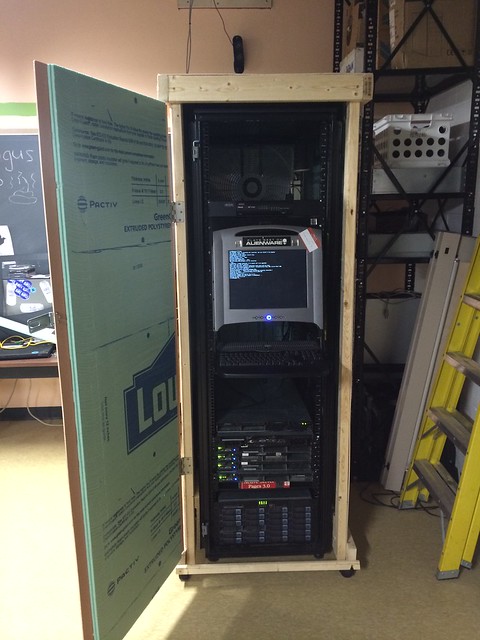
I previously worked on an enclosure for the Computer Club server rack, and I thought it would be a good idea to put together a standalone temperature sensor system. Preferably it would interface over the internet so that IRC bots and other programs could talk to it.
Here is the project, using an Arduino Uno for testing.

The project will use four DHT-11 temperature sensors, an ATMega 328 with an Arduino bootloader (for ease of programming), and an ENC28J60 ethernet module.
The microcontroller will take a temperature reading every few seconds, and when a connection comes in on its port 80, it will send back HTTP headers, text/json, and JSON data for easy parsing, in the following format:
{
  "sensor one": {
    "humidity": "34",
    "celcius": "25",
    "fahrenheit": "77"
  },
  ...
  "sensor four": {
    "humidity": "34",
    "celcius": "24",
    "fahrenheit": "75"
  }
}
The sensors are not all that accurate, so I cast the floating point values generated by the Adafruit DHT library to integers for reporting.
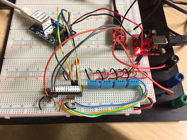
Here is the project built out on the breadboard.
The code, along with necessary libraries for this project is available here.
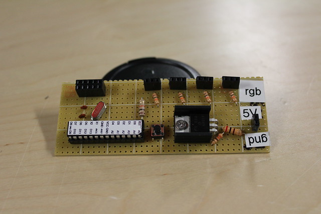
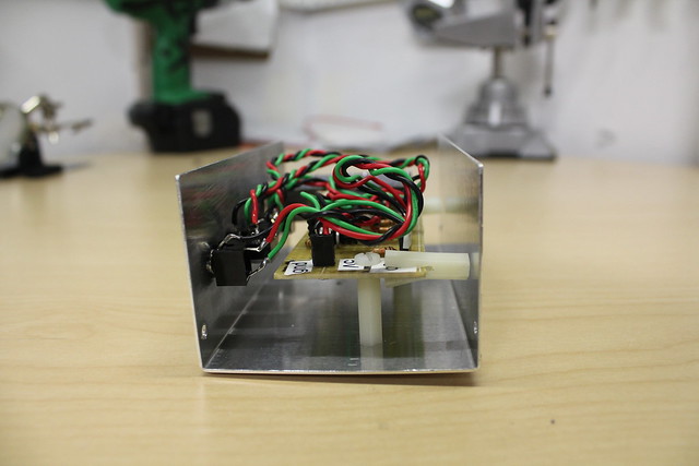
Building the project
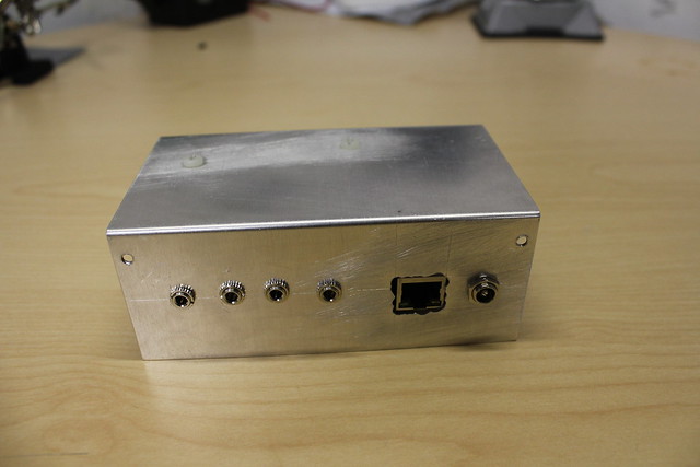
Since this project will live in a server rack, it needs to be put in a project box. The DHT11 and ENC28J60 module both need 3.3 volts, and the ATMega will run on 3.3 volts, so I used an LM317 voltage regulator to knock down 5 volts from a USB phone charger to 3.3 volts.
Running an ATMega 328 by itself is pretty simple, it needs a 16 Mhz clock connected between pin 9 and 10, and both of those connected to ground through a 10 uF capacitor. The, connect VCC, AVCC and AREF to 3.3 volts, and use a 10K ohm resistor to pull up RST.
Then, connect both GND pins to ground, and hook up a normally open switch to RST to ground.
For the DHT11 modules, each of them needs to be connected to 3.3 volts and ground, and each of their sensor output pins is pulled up to 3.3 volts with a 10K ohm resistor.
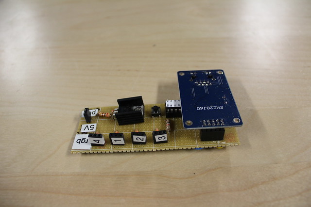
Finally, the ENC28J60 needs to be connected to 3.3 volts and ground, and its SPI bus connected to the pins as programmed on the microcontroller. I used female headers on the perfboard so that the module fits to the board, unmodified.
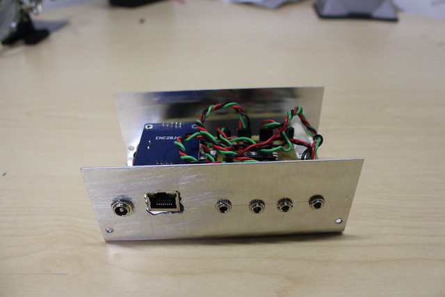
I used 3.5mm stereo audio jacks to connect the DHT11 modules. They each only need three pins to connect, so this is a convenient and cheap way to do it. Then, each DHT11 is wired to a length of stranded phone wire, terminated with a 3.5mm stereo plug.
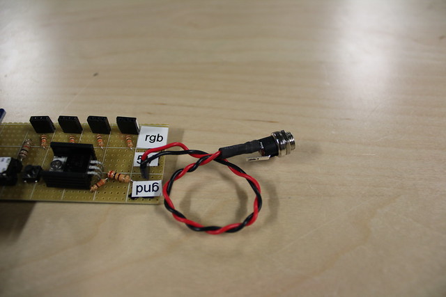
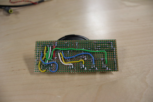
I used a spare DC barrel jack, wired to a USB cable. On the perfboard I used female headers and solid core wire to connect everything so that it is easy to take apart.